| Select Rooms
|
Click to select and deselect the rooms displayed in
the report. Clicking the icon changes the layout of the dialog. Rooms can be
selected/deselected individually by clicking on them, or select/deselect all by
clicking the two buttons provided.
-
Select all — Used to select all rooms
with a single click.
-
Deselect all — Used to deselect all
rooms with a single click.
-
OK — Applies all changes and closes the
Room selection view.
-
Cancel — Cancels all changes, and closes
the Room selection view.
|
| Design Data
|
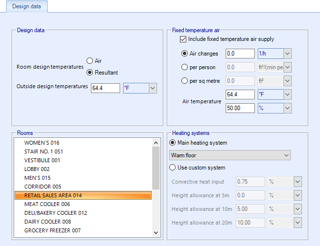
- Design
data:
- Room
design temperatures - Defines the room design temperatures for the
project as
Air or
Resultant temperatures.
- Outside design
temperatures - Sets the design temperatures for the peak month
(usually July) and the minimum month (usually January). Design temperatures for
the day of the calculation (e.g. June 15) are computed by assuming sinusoidal
temperature variations through the year, with a peak at July and minimum in
January. The actual design day for the calculation determines the position on
the sine wave and hence the maximum and minimum outside dry bulb temperatures.
Wet bulb temperatures are computed hourly, using a similar technique to dry
bulb.
The Outside design temperatures could be negative too.
- Fixed
temperature air - When
Include a fixed temperature air to rooms
is checked, the calculation is performed assuming a potentially infinite supply
of heating or cooling air at a done with a fixed temperature. Therefore the
calculated design air flow rate is always able to meet any load or change in
load no matter how large or abrupt. In reality air flow rates are limited by
duct sizes and fan capacities. Also enables the remaining air flow options
Air change,
per person,
per area, and
Air temperature.
- Rooms - Used to
select the rooms for running the calculation.
- Heating
systems:
- Main
heating system - Sets the standard heating system being used in the
heat loss calculation. The following default data is available for standard
systems:
| System
|
%Heat Conv.
|
Height Allowance (%)
|
|
|
|
16.4 ft (5 m)
|
32.8 ft (10 m)
|
65.6 ft (20 m)
|
| Warm
floor
|
33
|
0
|
0
|
0
|
| Warm ceiling
|
33
|
0
|
5
|
.
|
| Med/high temp rad. panels downward
|
10
|
0
|
0
|
5
|
| Natural warm convectors
|
90
|
0
|
5
|
.
|
| Forced warm air cross flow at low level
|
90
|
5
|
15
|
30
|
| Forced warm air downward from high level
|
100
|
5
|
10
|
20
|
| Med/high temp cross radiation, int. level
|
10
|
0
|
5
|
10
|
| Column radiators
|
80
|
0
|
5
|
.
|
| Double/triple radiator panels
|
70
|
0
|
5
|
.
|
| Single panel radiators
|
50
|
0
|
5
|
.
|
No heat gains are considered, except for
internal surfaces (partitions), where the specified adjacent temperature
results in a heat gain. The specified room height is used to determine the
height allowance, using room data stored within the program depending on the
heating system specified (see table of height allowances). The height allowance
is linearly interpolated between values, assuming an allowance of zero at floor
level. For rooms higher than 65.6 ft (20 m), the 65.6 ft (20 m) value is used.
If a system does not show a height allowance at some heights, this indicates
that the system should not be used in rooms of that height.
- Use
custom system - When on, you set the
Convective heat input and
Heigh allowance at 5m,10m,20m
options manually.
|
| Toolbar
|
Located along the top of each of the dialog tabs,
the toolbar provides controls for viewing, navigating, printing and exporting
reports.
The controls from left to right are:
- Navigate
back/forward in history - Disabled
- Stop - Click to stop
regeneration of the reports.
- Refresh - Click to
refresh the results being displayed.
- First page - Click
to jump to the first page of the report. Enabled when
"Switch to print preview" is selected.
- Previous page -
Click to jump to the previous page in the report. Enabled when
"Switch to print preview" is selected.
- Next page - Click to
jump to the next page in the report. Enabled when
"Switch to print preview" is selected.
- Last page - Click to
jump to the last page of the report. Enabled when
"Switch to print preview" is selected.
- Page setup - Opens
the Page Setup dialog.
- Switch to print
preview / interactive view - Click to change the layout of the report. The
print preview allows you to view each printed page. It activates the navigation
buttons (first, previous, next, last page). The interactive view (default)
displays the reports in a single scrollable page.
- Print report -
Prints the report.
- Zoom - Selects a
zoom factor from the available drop down menu.
- Close document map -
Click to hide/unhide the table of contents (left panel).
- Save - Used to save
as/export the report to the following formats:
- Acrobat (PDF)
file
- CSV (comma
delimited)
- Excel 97-2003
- Rich Text Format
- TIFF file
- Web Archive
|
| Dialog tabs
|
The dialog is divided into two main panels. A
selection panel (left) to select which portion of the report to display, and a
report display panel (right) to view, save and print the reports. See the
"tab" topic links below for details.
|
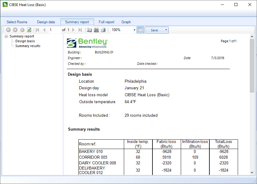
| Summary report tab
|
Used to
view a summary report of the results of the CIBSE heat loss
calculation conducted using the Basic Model steady state heat loss model.
|
| Full report tab
|
Used to
view a full report of the results for each room of the CIBSE heat
loss calculation conducted using the Basic Model steady state heat loss model.
|
| Graph tab
|
Used to
view a graphical report of the results for each room of the CIBSE
heat loss calculation conducted using the Basic Model steady state heat loss
model.
|
 Used to display results from the
CIBSE heat loss calculation conducted using the Basic Model steady state heat
loss model. The Basic Model, also referred to as the complex model, involves
carrying out a rigorous heat balance for the room, considering convective and
radiative heat transfer separately. The complex heat loss model calculation
results are often different from those obtained using the simple heat loss
model. It is considered more accurate results because it is based on a more
accurate analysis of room heat transfer, with fewer approximations.
Used to display results from the
CIBSE heat loss calculation conducted using the Basic Model steady state heat
loss model. The Basic Model, also referred to as the complex model, involves
carrying out a rigorous heat balance for the room, considering convective and
radiative heat transfer separately. The complex heat loss model calculation
results are often different from those obtained using the simple heat loss
model. It is considered more accurate results because it is based on a more
accurate analysis of room heat transfer, with fewer approximations.